In electrical engineering, electrical grounding or earth is the reference point in an electrical circuit from which voltages are measured, a common return path for electric current, or a direct physical connection to the earth.
What is the use of electrical grounding?
What Is Electrical Grounding? Grounding offers excess electricity the most effective and safest route from an appliance back to the ground by way of an electrical panel. Electrical grounding is a backup pathway that is generally only used if there is a fault in the wiring system.
Is electrical grounding necessary?
By grounding the electrical system, all the excess electricity will go into the earth instead of frying the appliances connected to the system. The appliances will be safe and protected from large electrical surges.
How to ground?
The function of electrical grounding determines the purpose of electrical grounding, and the purpose of electrical grounding determines the electrical grounding method. So which electrical grounding method is adopted depends on the type of electrical ground and the purpose of this type of electrical ground.
The purpose of electrical grounding determines the electrical grounding method. The same circuit, for different purposes, may have to adopt different electrical grounding methods. This point must be remembered.
For example, if the same circuit is used in portable equipment, the accumulation of static electricity cannot be discharged, and the purpose of grounding is to equalize the ground potential; when used in immovable equipment, there are generally safety grounding measures, and the purpose of electrical grounding for electrostatic discharge is to conduct electricity. The on-resistance is low enough, especially for the high-frequency on-resistance of spikes.
In terms of performance, electrical grounding is divided into four categories:
Safety grounding, work grounding (digital ground, analog ground, power device ground), anti-surge grounding (lightning surge, power-on surge), anti-static grounding.
The purpose of electrical grounding determines the grounding method, and the purpose refers to the function it realizes. Basically, all electrical grounding can be attributed to these four categories. Before each grounding, it is necessary to clarify which kind of grounding belongs to.
The goal of electrical grounding is low ground impedance, stable ground, and balanced ground.
The low-ground impedance is easy to understand. You can use a thick cable, but there is a problem that must not be ignored. For example, I grounded through a large inductor. If the fluctuation frequency of the ground current running on the ground wire is 0.00000001 Hz, this large inductor’s inductive effect is not obvious, which is equivalent to directly grounding, but if the fluctuating current is 1000000Hz, the inductance =jωL=j2πfL, it appears very large, in this case, it is equivalent to poor high-frequency grounding.
Why use a large inductance for electrical grounding? The first is that there is such a way in a certain state, and the second is that even if inductance is not connected in this way, the wiring inductance of ordinary cables cannot be ignored at high frequencies.
To sum up in one sentence, low-frequency grounding ≠ and high-frequency grounding. That is, low-impedance grounding should be analyzed whether it belongs to high-frequency or low-frequency grounding. If the grounding impedance is low enough, the ground current is easy to discharge, and there will be no voltage drop on the bottom line.
Ground balance is easier to be ignored. For a signal, the useful part is the voltage difference between the two wires. If the ground wire drifts, the voltage difference between the two wires and the ground wire will rise or fall equally, that is, the differential mode voltage. The value remains the same, and the common-mode voltage changes, and in fact, the circuit function is implemented as usual.
This situation is often used in electrostatic protection. An electrostatic pulse hits the circuit board through the air. For local circuits, the difference in distance will definitely cause an electrostatic induction pressure difference.
At this time, if a metal plate is used to separate it, even if the metal plate is floating, the circuit board behind the metal plate will induce a uniform electric field. Although the induced interference still exists, at least the circuit is basically balanced. It would be better if this metal plate is grounded.
Common mode voltage is generally not maintained, because the impedance of the transmission line is not uniform, and it will often turn into differential mode voltage interference. It is best not to let us face the problem of ground balance, but when there is no way, such as floating equipment, the circuit boards subject have to electrostatic be shocked, the ground balance should be considered when protecting them.
Common ground impedance coupling interference
Common ground impedance coupling interference is the core problem that we face every day in grounding, and it is almost inevitable.
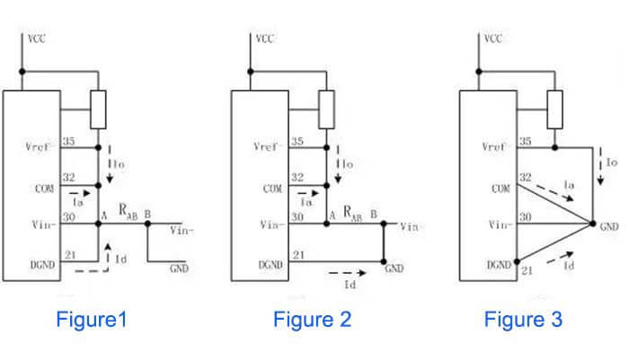
The following figure is an example. In Figure 1, the resistance of the RAB section is the common ground impedance part, and the three parts of the ground currents Io, Ia, and Id flowing through this section will affect each other in this section;
If the three currents are quite different, and the difference is 1-2 orders of magnitude, the mutual influence cannot be ignored, especially if a weak ground current branch is used for quantitative measurement, amplification, or AD conversion circuit when;
Figure 2 isolates the influence of Id on the other two roads;
Figure 3 shows that the three ground currents are all isolated separately.
General electrical grounding methods
The basic idea is to ensure that the safety protection ground, working digital ground, working analog ground, working power ground, lightning surge ground, and shielding ground are independently connected in the design.
The problem to be solved between various places is to deal with these grounds according to the following connection methods according to the purpose of electrical grounding.
The connection methods include:
Ground A
Direct connection of yellow and green wires between grounds
This kind of connection is best understood, that is, simply make the two grounds reliable and low-impedance conduction. But remember, this kind of connection is limited to the connection between the medium and low-frequency signal circuit grounds.
Because this kind of wire has a certain trace inductance and trace resistance, the cable acts as a large impedance for high-frequency fluctuation ground currents, which is equivalent to low-frequency grounding, and high-impedance grounding at high frequencies, It is basically unable to achieve reliable conduction at high frequencies.
Ground B
Direct connection with a wide flat cable between grounds
The flat cable is mainly to solve the above problem that the direct connection of the wires cannot be solved. The grounding cable of the electrostatic test bench does not use a straight line. It can realize the ground impedance to the ground at high frequency.
Ground C
Large resistance connection between grounds
The characteristic of a large resistor is that once there is a voltage difference between the two ends of the resistor, a very weak conduction current will be generated. After the charge on the ground line is discharged, the voltage difference between the two ends is finally =0V. This feature is in the hope that the charge discharges. But I don’t want it to be fully displayed when it is released quickly.
The on-resistance of the anti-static table mat at the production worksite is generally 106-109 ohms, which is the purpose. The anti-static table mat is equivalent to a large resistance between the ground of the working circuit board and the protective ground.
The characteristics of the capacitor connected to the capacitor between C and ground are DC cutoff and AC conduction. This method can be considered for occasions that wish to realize this type of function.
For example, for a product powered by a switching power supply, the shell is connected to the protective ground, and the ground on the circuit board inside has chaotic fluctuation interference, but there is no place to discharge it, cross the 24V, 12V, 5V, etc, of DC power ground and the protective ground. Connect a large capacitor, the fluctuation can be released, but the DC component can be guaranteed to be relatively stable;
Note that in this case, if the stability of the protective ground and the enclosure ground cannot be guaranteed, the effect may be counterproductive.
Ground D
Magnetic bead connection between grounds
Here, the characteristics of magnetic beads need to be clarified. Many engineers often equate magnetic beads with inductance. This is a fundamental mistake. The magnetic bead is equivalent to a resistance that changes with frequency. It shows resistance characteristics and is lossy;
Inductance is of the nature of energy storage. Therefore, there is generally a state of rapid small current fluctuations between the grounds of the magnetic beads, because the magnetic beads will saturate, and the current is too large for it to consume. It is generally used between the weak signal ground and the ground.
Ground E
The inductance has the characteristics of restraining the change of the circuit state. Through the connection of the inductance, the peak can be pinned and the valley can be filled. For the ground, the ground, and the cross-inductance with large current fluctuations, this problem can be solved.
Ground F
Small resistance connection between grounds
The problem to be solved by the small resistance is to add damping to hinder the overshoot of the rapid change of the ground current. When the current changes, the rising edge of the inrush current is slowed, which is equivalent to the crystal oscillator output terminal and the bus output terminal to reduce overshoot and ringing matching resistance.
The connection method of safe ground and anti-lightning surge electrical grounding
Because the current of the lightning surge and safety ground is generally much greater than the harm of signal current to humans, it is recommended that these two groundings be connected to the ground separately and connected at a single point on the real ground, especially the lightning protection electrical grounding.
Besides the What Is Electrical Grounding article, you may also be interested in the below articles.
PCB Antenna VS. External Antenna
Ceramic Antenna VS. PCB Antenna, A Comparison Guide
Wifi vs. 5G, is 5G better than Wifi?
Mobile Networks’ Evolution From 1G To 5G