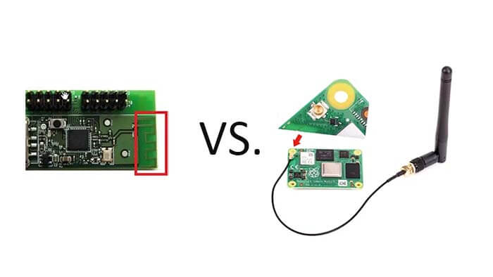
PCB antenna VS. external antenna, what is the different between the embedded PCB antenna and external antenna?
What is a PCB antenna?
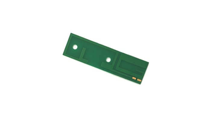
PCB antenna is the part on PCB for wireless receiving and transmitting. PCB antenna structure can be monopole, dipole, slot, patch, and planar inverted F (PIFA).
PCB is an important electronic component, is the support body of electronic components, and is the carrier of electronic components’ electrical connection. Since it is made by electronic printing, it is called a printed circuit board.
What is an FPC antenna?

PCB has rigid PCB and flexible PCB; the flexible PCB antenna is also called an FPC antenna. The antenna designed on the flexible PCB circuit trace board is an FPC antenna.
The antenna is a key component of many wireless systems. Printed circuit board (PCB) antenna has a wide range of applications in the industry due to its small size and easy integration with other high-frequency circuits.
What is a PCB onboard antenna?
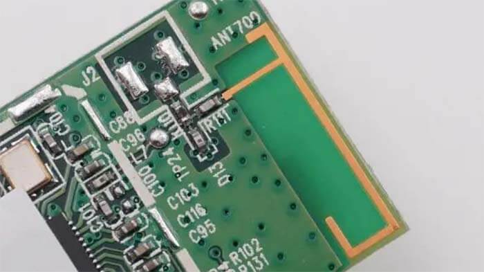
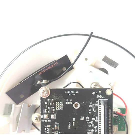
The onboard antenna directly uses PCB as the medium. The antenna is realized by PCB process, testing, and use without assembling the antenna separately. Not easy to touch damage and easy to assemble.
This PCB onboard antenna is widely used in WiFi modules, Bluetooth modules, ZigBee, and other wireless modules in the 2.4 GHz band.
It is important to note that these PCB onboard antenna WiFi modules also support external antennas for IPEX holders. When making a WiFi module selection, customers can select the antenna version according to the actual demand.
What is an external antenna?
Whether an antenna is internal or external depends on whether the antenna is installed inside or outside the terminal equipment. The antenna installed inside the terminal equipment is called an internal antenna, and the antenna installed outside the terminal equipment is called an external antenna.
The external antenna includes external omnidirectional and directional antenna types. External only means the antenna is placed inside or outside the terminal equipment, and omnidirectional and directional means the radiation direction of the antenna.
The main types of external antennas
1/4 wavelength monopole whip antenna type
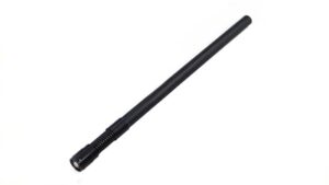
Half-wavelength dipole rubber duck antenna type
Spiral / helical antenna type
Basic performance parameters of the antenna
Gain (dBi)
Under the same input power, the ratio of the radiated power of the antenna at a point in space and the power of the ideal non-directional point source antenna at the same point, the gain unit, is dBi.
The manufacturers provide the antenna test report in the gain, generally in dBi as the unit.
Gain (dBd)
In the same input power, the antenna in space at a point of the radiated power and the ideal half-wave dipole antenna maximum radiation direction of the power ratio, the unit of the gain is dBd.
For example: for a gain of 0 dBd antenna, its gain converted into a dBi unit is 2.15dBi.
Directivity
In the same radiation power, an antenna in space at a point of power and the ideal non-directional point source antenna at the same point of the power ratio.
Efficiency
Antenna radiation power and the ratio of antenna input power.
Gain=Directivity × Efficiency
Efficiency=Output Power/Input Power
APIP (Antenna Port Input Power)
The amount of power added to the antenna port is the amount of power output from the PA to the antenna port. The power level is mainly related to the conducted transmit power level of the mobile device.
EIRP (Effective Isotropic Radiated Power)
The equivalent omnidirectional radiated power is the product of the power Pt supplied by the radio transmitter to the antenna and the absolute gain Gt of the antenna in a given direction, reflecting the power magnitude of the antenna in each direction.
EIRP expressed the combined effect of transmitting power Pt and antenna gain Gt.
EIRP is the power of a theoretical isotropic antenna (uniformly distributed in all directions) to produce the peak power density observed in the direction of maximum antenna gain. It is also referred to as the equivalent isotropic radiation power.
EIRP can consider the loss of transmission lines and connectors, including the antenna gain.
EIRP=Pt × Gt
Pt: the power supplied by the transmitter to the antenna in dBm
Gt: indicates the antenna gain of the transmitting antenna. The unit is dBi
If calculated in logarithm (dB), it is:
EIRP = P – Loss + G
P: the output power of the transmitter in dBm
Loss: the output of the transmitter and the antenna feed between the feed line loss, in dB
G: the transmit gain of the antenna, in dBi
PEIRP (Peak Effective Isotropic Radiated Power)
The PEIRP is peak equivalent isotropic radiated power.
ERP (Effective Radiated Power)
Radio transmitter supply antenna power and the product of the antenna in a given direction relative to the gain of the half-wave dipole oscillator.
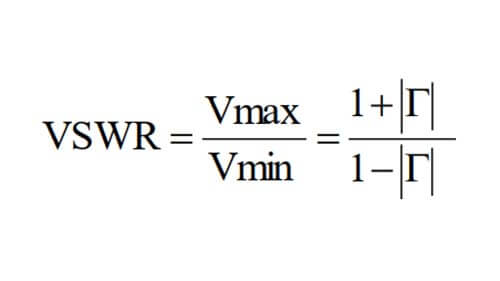
Voltage standing wave ratio formula:
The basic requirements of the antenna
Frequency band according to the equipment needed to work frequency
VSWR ≤ 3
Gain (dBi) ≥ 1
Maximum input power (W) 50
Input impedance (Ω) 50
Polarization type Line polarization: vertical, horizontal
Circular polarization: left-rotation, right-rotation
PCB antenna VS. external antenna, what is the different?
The advantages and disadvantages of PCB antenna
PCB can be increasingly widely used because it has many unique advantages.
High-density
For decades, the printed board’s high density can be developed with the progress of integrated circuit integration and installation technology.
High Reliability
Through a series of inspection, testing and ageing tests, PCBs can be guaranteed to work reliably for a long time (life, generally 20 years).
Designability
Various performance (electrical, physical, chemical, mechanical, etc.) requirements for PCBs can be standardized and standardized through design to achieve printed board design quickly and with high efficiency.
Producibility
With modern management, standardization, scale (quantity), automation and other production can be carried out to ensure consistent product quality.
The advantages and disadvantages of external antenna
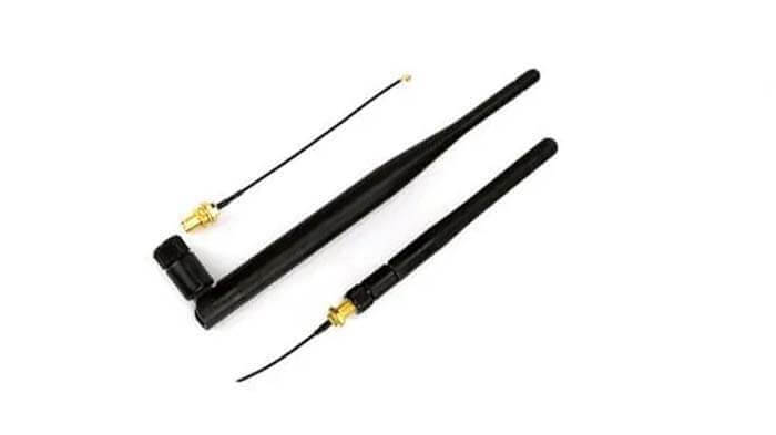
IPEX/SMA antenna is a kind of interface between an RF circuit and an antenna, mostly rubber duck antenna and widely used on wireless local area network (WLAN) related products.
IPEX/SMA interface external antenna, its advantages are the good directional direction of the signal, high efficiency, strong anti-interference ability, can be away from the interference on the motherboard, and not need too much-debugging matching, as a terminal manufacturer, only need to connect an antenna with IPEX/SMA connector outside;
Of course, there are disadvantages: high cost and not as beautiful as the embedded PCB antenna.
Compared with PCB antenna, the advantage of IPEX/SMA external antenna is reflected in the optional antenna type is more, and can be connected to a large gain external antenna to improve the sensitivity of the received signal, to meet the demand for data transmission over a slightly longer distance.
What is the difference between a PCB antenna and an external rubber duck antenna?
PCB antenna:
The PCB antenna can be simply regarded as a microstrip antenna.
Microstrip antenna technology is the antenna of printed circuits established after fully considering various distribution parameters, which is a major progress of antenna technology following computer model design.
Practical, simple printed copper strip piece only, can make full use of the shape and space of the object.
General external antenna rubber duck antenna:
The best resonance of the relationship between the traditional technology’s conductor space size and the electric wave’s size.
Embedded PCB antenna vs. external antenna, which signal is better?
Embedded PCB antenna vs. external antenna, which signal will be better?
It is one-sided to judge the signal as good or bad only by the external or internal antenna. In recent years, many test studies have shown that built-in antenna routing signal strength is not inferior to the external antenna in the same environment and is beautiful and space-saving.
You can refer to the cell phone about whether the embedded PCB antenna will affect the signal. In the past, mobile phone antenna was also external, but now the antenna of cell phones is invisible.
The embedded PCB antenna does not affect our daily reception of signals and calls. In addition to cell phones, TV sets are also an example. From the current trend, the built-in antenna will gradually replace the external antenna to become mainstream.
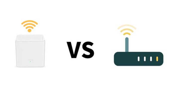
Whether external or internal, they are just a design solution for wireless router antenna; it has nothing to do with signal strength.
How to design an antenna on PCB?
The onboard antenna PCB antenna design guides and PCB design considerations are below.
It is recommended to place the module with the RF port to the outside;
RF alignment try not to punch holes, change layers;
RF alignment needs to do 50Ω impedance control and ensure that the RF port to the antenna alignment is the shortest;
If the RF port is far from the antenna, it is recommended to use the RF line connection;
Antenna feed point as far as possible on the edge of the PCB board area, not on the inside of the PCB board;
For two antennas with similar frequency bands, the distance between the two antennas should be beyond 1/4 wavelength of the lowest frequency if the environment allows;
When the distance is too close, you can try orthogonal placement;
In general, the isolation between the two antennas should be at least 10dB to avoid mutual interference;
Please place the antenna as far as possible from CPU/SDRAM/Flash/DC-DC/USB/screen, etc. It is recommended that the antenna and the above devices are placed on the opposite side of the surface and bottom of the PCB;
The high-speed lines between CPU and SDRAM/Flash/Screen FPC should be as short as possible, and go to the inner layer, with the top, bottom, left, and right wrapped well; it is recommended to add EMI filters to the high-speed lines between CPU and screen;
It is recommended to put the CPU/SDRAM/Flash/DC-DC/screen connector inside the shield;
The shield is recommended to be made of white copper.
Besides the PCB Antenna VS. External Antenna article, you may also be interested in the below articles.
Ceramic Antenna VS. PCB Antenna, A Comparison Guide
Wifi vs. 5G, is 5G better than Wifi?
Mobile Networks’ Evolution From 1G To 5G
How To Choose Embedded Antenna For IoT?