For the FPC antenna design guidelines, we mainly talk about the below four points.
FPC antenna structure design guidelines
FPC antenna material selection
FPC antenna assembly process requirements
FPC antenna reliability test requirements
For handheld, wearable design, smart home, and other small-size IoT products, rarely use an external antenna and generally use the built-in antenna, built-in antenna mainly includes a ceramic antenna, PCB antenna, FPC antenna, spring antenna, etc. The following article is for the introduction of built-in FPC antenna design guidelines.
FPC antenna advantages: applicable to almost all small electronic products, can do 4G LTE full-bands such as more than ten bands of complex antenna, good performance, the cost is relatively low.
FPC antenna disadvantage: need to debug according to each product individually.
FPC antenna structure and tolerance specification
FPC antenna design size tolerance
FPC antenna size tolerance is generally ±0.15mm if more than 80 less than 100 according to ±0.20mm.
Antenna tolerance of ± 0.30mm, because the ink diffusion in the printing process will overflow.
The positioning hole center’s distance tolerance ± 0.10mm, the minimum slot width of 0.8mm.
Due to material deformation, mold punching deviation, to meet the product performance and appearance of the premise, the appropriate relaxation of tolerance, one is conducive to production operations; the second is conducive to improving the product qualification rate, reducing costs.
FPC antenna structure Stress hole/slot design
FPC antenna in the intersection of the bend lay copper, the width as far as possible to control within 1.0mm, otherwise must set the stress relief hole/slot or needle cut line to reduce the internal stress.
FPC antenna housing design
If the FPC antenna is in the outer housing surface, the FPC antenna area needs to sink 0.3mm (FPC thickness 0.15mm) and the housing surface made of 22~24# spark pattern, grain surface than glossy paste effect is good, not easy to warp.
FPC antenna commonly used positioning method is divided into positioning column/hole positioning or boundary positioning; (positioning column diameter Φ0.8X0.3H; boundary positioning single side gap 0.05-0.1mm.)
FPC antenna area tries not to make curved surface because the curved surface stick FPC will wrinkle, long time placing will also warp, thus affecting the antenna performance and beauty.
Solution:
Try to change the curved surface into a slope. If you can only do the curved surface, it must be a single-direction curved surface.
Such as some FPC antenna is printed in double-sided ink leads to local buckling. A curved surface or bevel can effectively avoid buckling if the shell is designed in a single direction.
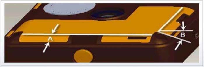
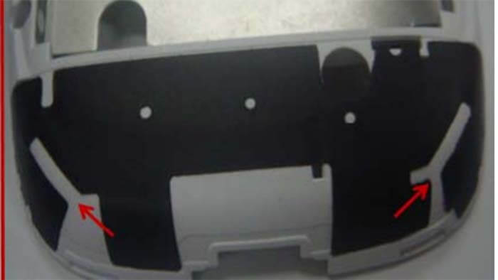
Antenna FPC and antenna cover film are often used on the top surface and the surrounding side, needing to bend, and bending easily to produce warping problems. The antenna warping problem has occurred in many models. Three sides are single surfaces. Although the curvature is not large, the production was found warping. After analysis and verification, the antenna can effectively improve the warping problem by changing the curved surface of the side to a flat surface.
1) The gluing width A of the side plane should be more than 4mm.
2) Side plane bending angle B Side plane bending angle can be from 0-90 degrees. The larger the angle is, the wider the side plane should be after overbending.
(3) Excessive R angle R0.2-0.4mm can be taken.
(4) FPC in the excessive R angle to hit the process hole (recommended diameter of ≥ 0.8-1.2mm) can reduce the bending stress.
FPC antenna structure corner design
The FPC antenna laying copper edge is at least 2mm from the PI edge for the shape corner parts. When the antenna must lay copper to the edge of the FPC antenna, it is necessary to continue extending the FPC antenna and then bending it to the inside of the structural part.
FPC antenna design structure cracking slot design
It is necessary to set the cracking width> slot (slot width 1mm) to prevent wrinkling and warp in some large shell arc surfaces.
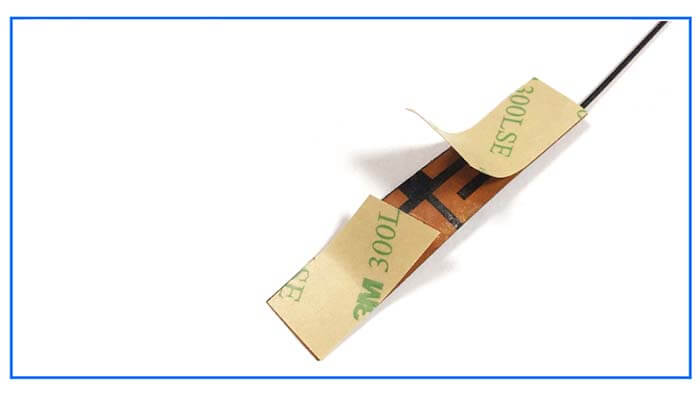
Adhesive sticker in FPC antenna design
The antenna release paper must be cut in sections according to the pasting steps to ensure that the operator will not touch the adhesive backing. It is recommended to place the positioning pillar on the first step of the paste. It is to facilitate effective positioning. The release paper open line is usually set in the middle of the two positioning holes to tear off half of the alignment first and then tear off the other half of the sticker.
The choice of FPC antenna material
- FPC antenna ink is mainly composed of epoxy resin plus related filler.
Usually with the thermosetting oil after a dummy, silk ink needs to be heated and baked to dry. Generally, choose light black bright white green; printed resist thickness of 0.015mm-0.02mm. The most common problem is ink cracking, so wear resistance, adhesion, foldability, ink thickness, Acid and alkali resistance, ultraviolet light, and other tests.
- FPC antenna copper foil usually uses electrolytic copper or calendering copper.
The thinner the overall thickness is not easy it to warp, with the recommended overall thickness of 0.12mm. The material needs to choose PI18/12.5 or PI18/25 (PI half and half is softer, not easy to warp, preferably PI half and a half), and generally do not consider using PET.
- FPC antenna adhesive is according to the bonding characteristics, such as the need for high-temperature-resistant.
The 3M adhesive sticker (0.05mm) has an excellent bonding effect, good processability, good temperature resistance, anti-corrosion, and good holding adhesive force;
It has long-term temperature resistance. Short-term temperature resistance also can be.
- The total thickness of the finished FPC antenna:
ink+substrate+copper foil+backing adhesive total thickness 0.12mm-0.15mm.
- FPC antenna nickel gold plating.
General use of chemical replacement gold plating and electroplating two kinds of gold plating, must first nickel plating and then gold plating, which is to prevent gold atoms and copper atoms from penetrating each other, resulting in gold layer instability;
Two processes compared, the electroplating process gold thickness can do more than 0.3um or even thicker;
And chemical plating gold thickness can only be <0.075um; because FPC plating does not have bending toughness, and the thicker the gold plating cost, the higher the cost. It is recommended that the gold thickness control: is 0.025um-0.075um.
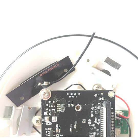
FPC antenna assembly process requirements
- FPC antenna paste before the structure must ensure that the surface clean, such as apparent oil, need to be cleaned or ultrasonic cleaning; it requires shell material manufacturers to use vacuum plasma equipment for surface activation treatment of structural parts.
- The FPC paste environment requires a high degree of cleanliness in the space.
- FPC paste requires the operator to operate with finger gloves so as not to leave fingerprints and sweat after the backing touches the hands and affects the bonding quality.
- Use glue for local easy-to-warp parts, primer, or activator treatment.
- Paste, ask the operator to tear the antenna end from the release paper first, align it with the paste part of the product, and tear and paste until the paste is finished, do not touch the antenna in the process.
- The shell surface is as far as possible to make a 24# spark pattern, grain surface than glossy paste effect is good, and injection cannot play release agent, spraying to eliminate the antenna area of the flying oil. For example, the shell flying oil causes the FPC antenna to buckle to produce the FPC paste smoothly before the shell has oil parts coated with 3367 activators.
- To ensure the consistency of the FPC paste, no positioning column, and positioning holes of the antenna paste, it is recommended to use the fixture positioning assembly.
FPC antenna reliability test requirements
- testing instruments/ tools: salt spray test chamber, film thickness tester, cotton cloth, gasoline, abrasion tester, cold and heat shock, constant temperature and humidity chamber, QUV accelerated erosion tester, colorimeter, imported eraser.
- FPC antenna design applications: applicable to all wireless network connections that FPC antenna can use.
C&T RF Antennas Inc provides the PCB antenna design and FPC antenna design service, the antenna design includes 5G NR FPC Antenna design, 4G FPC Antenna design, 3G FPC Antenna design, NB-IoT FPC Antenna design, Wifi FPC Antenna design, GPS FPC Antenna design, LoRa FPC Antenna design, etc. Contact us for more antenna design information you may need.
Besides the FPC Antenna Design Guidelines article, you may also be interested in the below articles.
PCB Antenna VS. External Antenna
Ceramic Antenna VS. PCB Antenna, A Comparison Guide
Wifi vs. 5G, is 5G better than Wifi?
Mobile Networks’ Evolution From 1G To 5G