Description
What is a High-performance 4G Network Antenna LTE PCB Antenna?
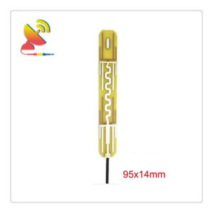
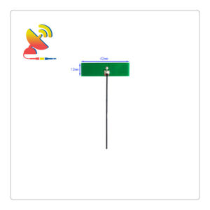
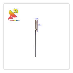
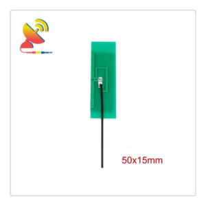
The High-performance 4G Network Antenna LTE PCB Antenna CTRF-ANTENNA-PCB-7027-6016-IPEX is a 4/6dBi gain high gain 4G internal antenna LTE PCB antenna manufactured by C&T RF Antennas Inc for 3G 4G wireless network applications.
The High-performance 4G Network Antenna LTE PCB Antennas are available at C&T RF Antennas Inc., the RF antennas LTE 4G antenna manufacturer in China.
C&T RF Antennas Inc provides RF antennas with PCB & Flex PCB & Omni antenna types, covering the below frequencies:
5G NR PCB Antennas, LTE PCB Antennas, GSM PCB Antennas, Wifi PCB Antennas, NB-IoT PCB Antennas, LoRa PCB Antennas, GPS PCB Antennas;
5G NR FPC Antennas, 4G FPC Antennas, 3G FPC Antennas, NB-IoT FPC Antennas, Wifi FPC Antennas, GPS FPC Antennas, LoRa FPC Antennas;
5G Omni Antennas, 4G Omni Antennas, Wifi Omni Antennas, LoRa Omni Antennas; etc.
Contact us for more information on the High-performance 4G Network Antenna LTE PCB Antenna such as the 4G Network Antenna LTE PCB Antenna datasheet, 4G Network Antenna LTE PCB Antenna pricing, 4G Network Antenna LTE PCB Antenna inventory, or other 4G LTE antenna designs.
High-performance 4G Network Antenna LTE PCB Antenna Specifications
High-performance 4G Network Antenna LTE PCB Antenna Electrical Specifications |
|
| RF Antenna Type | PCB Antenna |
| Model | CTRF-ANTENNA-PCB-7027-6016-IPEX |
| Frequency | 698-960MHz, 1710-2700MHz |
| Gain | 4dBi/6dBi |
| VSWR | ≤2.0 |
| Impedance | 50 Ω |
| Polarization | Linear |
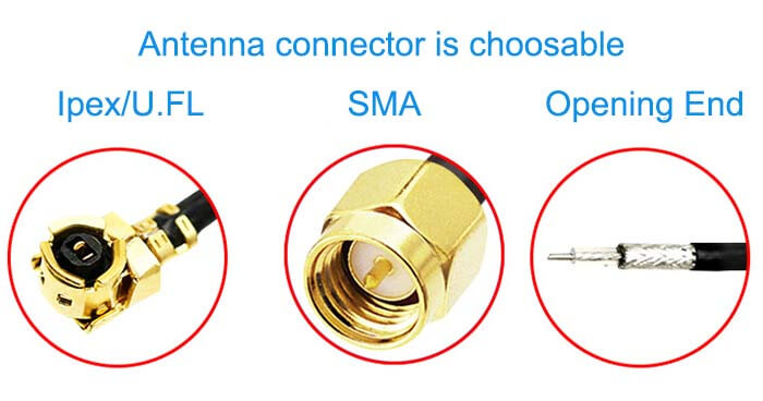
| Connector | U.FL/Ipex/MHF |
| Lightning Protection | DC-Ground |
High-performance 4G Network Antenna LTE PCB Antenna Mechanical Specifications |
|
| PCB Board Dimension | 60*16mm |
| Weight | Approx. 10g |
| Material | PCB Board |
| Operation Temperature | -40˚C ~ +85˚C |
| Storage Temperature | -40˚C ~ +80˚C |
| Color | Green |
| Antenna Design | Dipole Antenna |
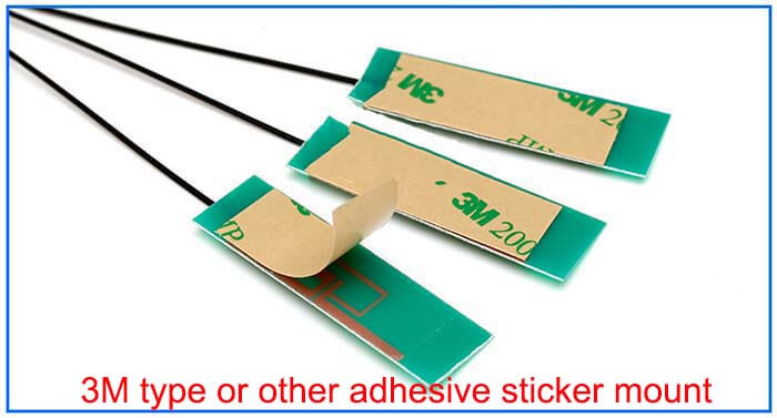
| Mounting | Screw/Sticker |
| SafetyEmission and other | RoHS Compliant |
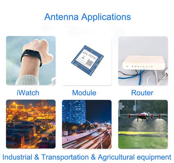
| Applications | ISM/SCADA/Utilities, IoT/NB-IoT/LoRa/M2M, 2G 3G 4G LTE/LTE-IoT, GSM GPRS UMTS WCDMA, etc. |
TDD technology allows flexible setting of uplink and downlink transition moments for achieving asymmetric uplink and downlink service bandwidth, which is conducive to realizing Internet services with significant uplink and downlink asymmetry.
However, the setting of such transition moments must be performed in cooperation with adjacent base stations.
Compared with FDD, TDD can use fractional frequency bands because the upstream and downstream are differentiated by time and do not need to require bandwidth-symmetric bands.
TDD technology does not require a transceiver isolator, only a switch is required.
Mobile station movement speed is limited.
When moving at high speed, the Doppler effect causes fast fading. The higher the speed, the higher the fading transformation frequency and the deeper the fading depth, so the moving speed must be required not to be too high.
For example, in a TD-SCDMA system that uses TDD, based on the current chip processing speed and algorithm, when the data rate is 144kb/s, the maximum mobile speed of TDD can reach 250km/h, which is still a certain gap compared with FDD system.
The general TDD mobile station can only reach half of the FDD mobile station’s mobile speed or even lower.
Transmitting power is limited.
If TDD wants to send the same amount of data as FDD, but the transmitting time is only about half of FDD, it requires TDD’s transmitting power to be high. Of course, it also requires more complex network planning and optimization techniques.
High-performance 4G Network Antenna LTE PCB Antenna Features

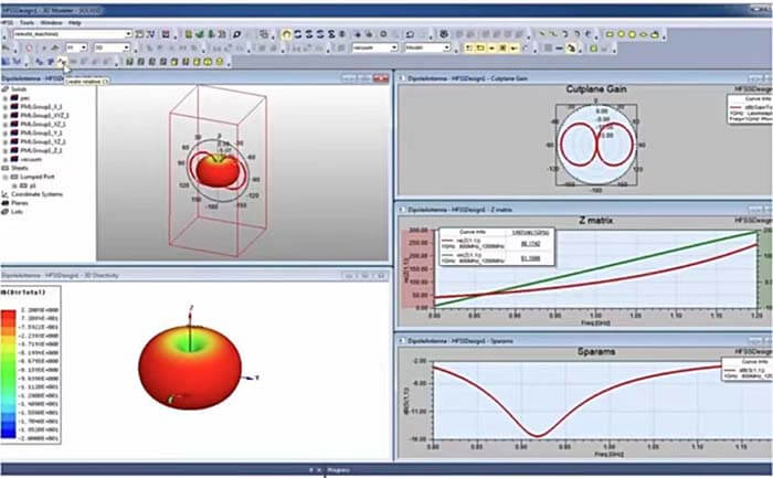
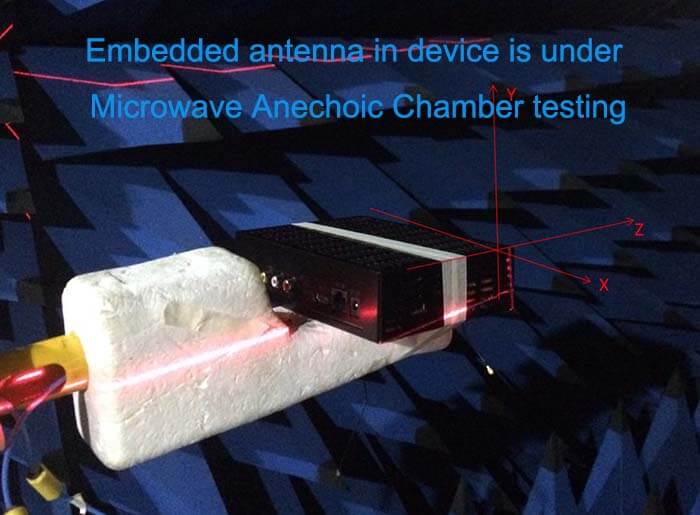
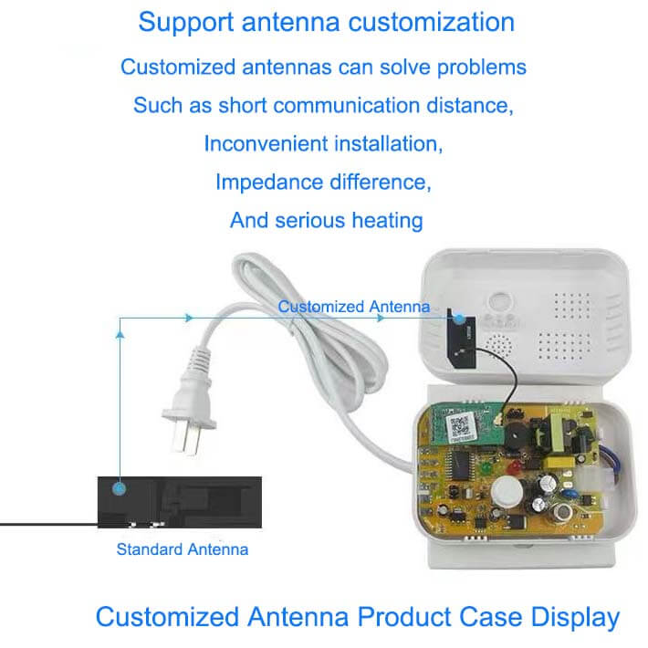
Customized Antenna Design

Reviews
There are no reviews yet.