Description
What is a 4G LTE 5G NR Flexible PCB Antenna?
The embedded antenna 4G LTE 5G NR Flexible PCB Antenna CTRF-ANTENNA-FPC-60600-6515-IPEX is an Omni dipole antenna Flex PCB-style antenna for 5G New Radio, LTE, and cellular IoT (LTE-M, NB-IoT) applications.
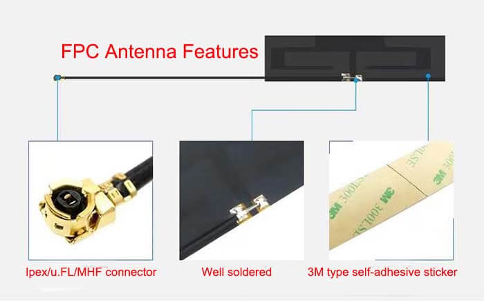
The 4G LTE 5G NR Flexible PCB Antenna comes with a 65x15mm flexible print circuit board antenna size, Ipex connector, 120 mm cable length, RG 1.13 cable antenna extension, self-adhesive sticker mount FPC antenna for New 5G applications.
What are the 4G 5G NR Antenna Applications?
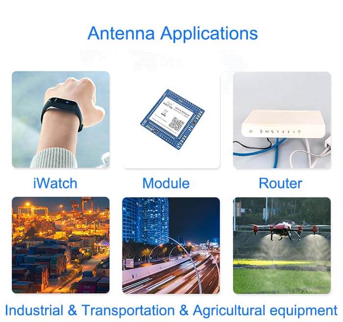
GSM/GPRS/5G NR/4G LTE/3G/2G/NB-loT full-band network equipment, such as routers, DTUs, wireless monitoring, wireless modules, smart homes, etc.
The 4G LTE 5G NR Flexible PCB Antennas are supplied by C&T RF Antennas Inc, the RF antennas 5G New Radio antennas manufacturer in China.
C&T RF Antennas Inc provides RF antennas with PCB & Flex PCB & Omni antenna types, covering the below frequencies:
Contact us for more information on the 4G LTE 5G NR Flexible PCB Antenna such as 4G LTE 5G NR Flexible PCB Antenna datasheet, 4G LTE 5G NR Flexible PCB Antenna pricing, 4G LTE 5G NR Flexible PCB Antenna inventory, or other 4G 5G NR antenna designs.
4G LTE 5G NR Flexible PCB Antenna Specifications
4G 5G NR Antenna Electrical Specifications |
|
| RF Antenna Type | Embedded FPC Antenna |
| Model | CTRF-ANTENNA-FPC-60600-6515-IPEX |
| Frequency Center | 600-6000MHz |
| Gain | 8dBi |
| VSWR | ≤3.0 |
| Impedance | 50 Ω |
| Polarization | Vertical Polarization |
| Cable Type | RG1.13 |
| Connector | IPEX |
| Cable Length | 130mm |
| Lightning Protection | DC-Ground |
4G 5G NR Antenna Mechanical Specifications |
|
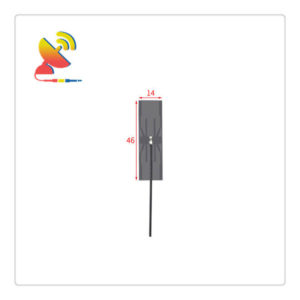
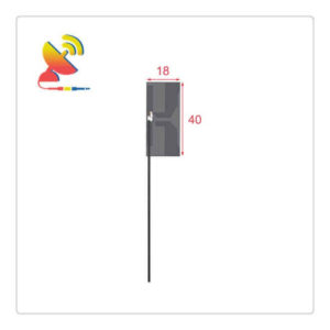
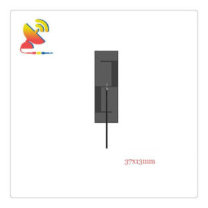
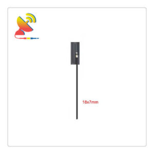
| FPC Board Dimension | 65x15mm |
| Weight | 6g |
| Material | FPC |
| Operation Temperature | -40˚C ~ +85˚C |
| Storage Temperature | -40˚C ~ +80˚C |
| Color | Black |
| Antenna Design | Omni Dipole Array |
| Mounting | Connector |
| SafetyEmission and other | RoHS Compliant |
| Applications | Public Safety/LMR/P25/TETRA, ISM/SCADA/Utilities, RFID, Wifi, GPS, GNSS, IoT/NB-IoT/LoRa/2G/3G/4G, GSM/GPRS/LTE/5G/6G |
5G MIMO and Massive MIMO Technology
Massive MIMO technology is an extension of MIMO technology, which efficiently and repeatedly utilizes the same bandwidth in order to transmit more data and achieve more efficient use of the spectrum.
As 4G moves to massive MIMO, the number of antennas increases exponentially to 16, 32, 64, 128, and even more. The collection of these antennas is known as an “antenna array system” (AAS).
This helps to concentrate energy into smaller spatial areas by means of beamforming techniques (see next section), which greatly improves throughput and radiated energy efficiency.
Massive MIMO helps to prevent data from being transmitted in non-ideal directions and mitigate interference;
Reduce latency, thereby increasing speed and reliability;
Reduce notification and connection fading and dropouts;
Simultaneously serve large user populations;
Introducing two-dimensional beamforming.
Massive MIMO not only increases cellular capacity and cellular efficiency but also enables RF signals to be transmitted and received in parallel using a sharp antenna beam direction map (consisting of multiple antenna elements).
At a base station using massive MIMO technology, each data stream has a unique radiation direction map and therefore does not interfere with each other. The signal strength of each data stream is transmitted in the direction of the target user device; in the direction of other user devices, the signal strength is reduced to reduce interference.
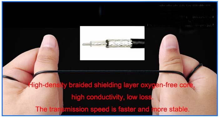
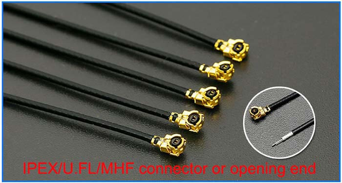
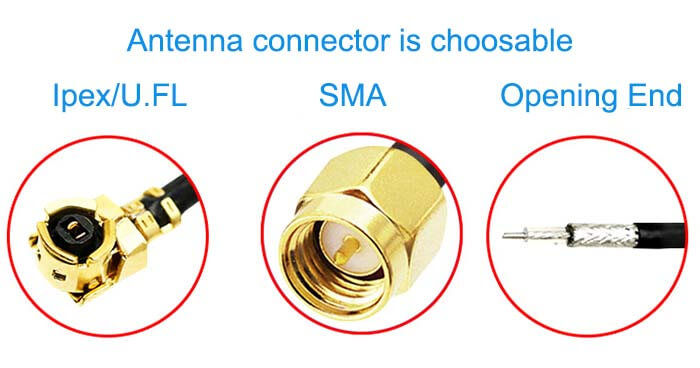
Embedded Flex PCB / FPCB Antenna Features

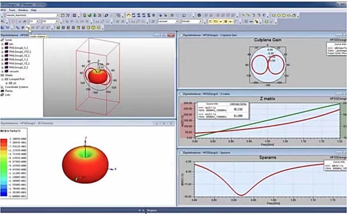
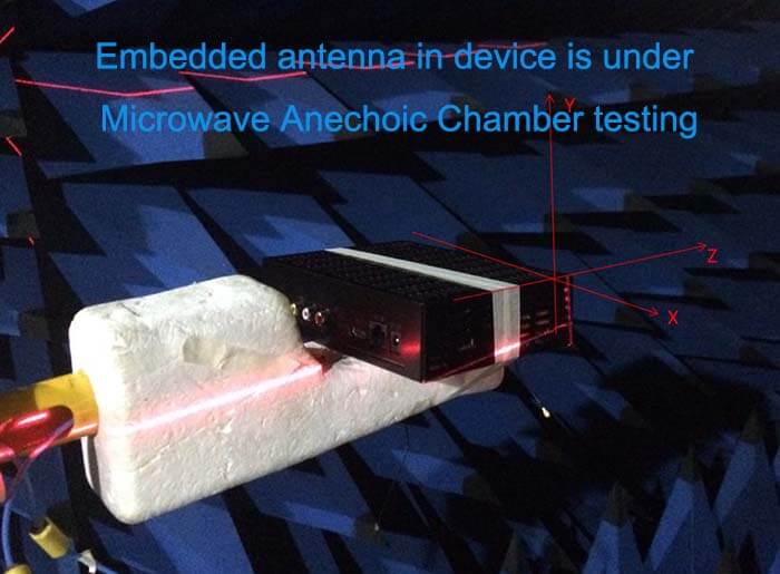
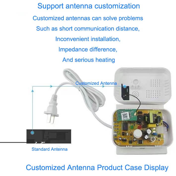
Customized Antenna Design

Reviews
There are no reviews yet.