Description
What is Internal LTE Antenna PCB 4G Antenna?
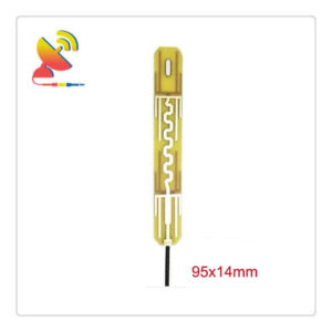
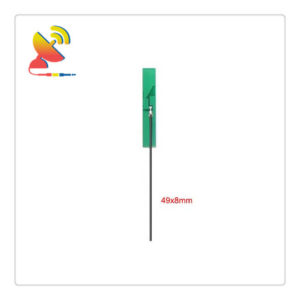
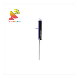
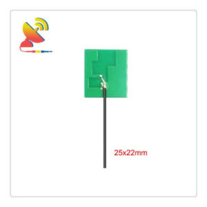
The Internal LTE Antenna PCB 4G Antenna model CTRF-ANTENNA-PCB-7027-4410-IPEX-120 is a 4G internal antenna PCB-based circuit board antenna manufactured by C&T RF Antennas Inc for wireless networks applications.
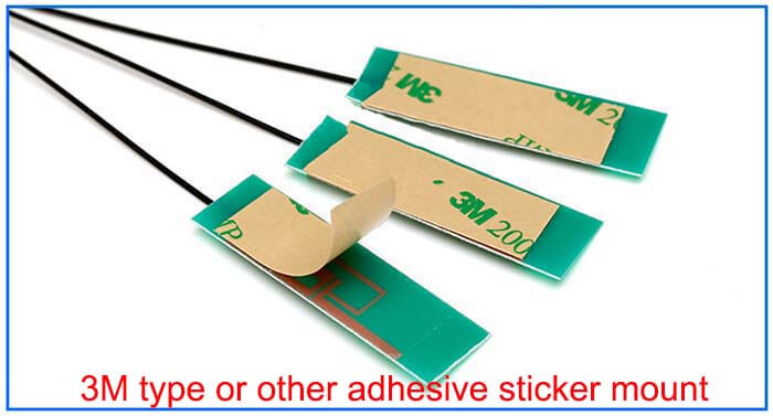
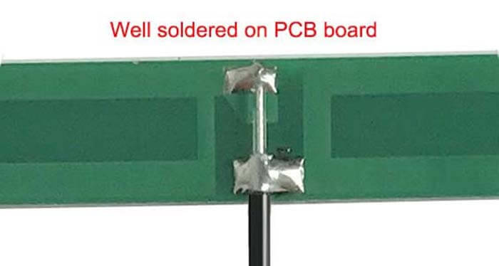
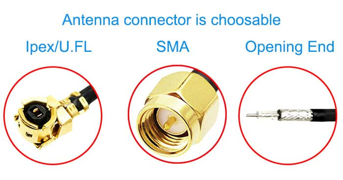
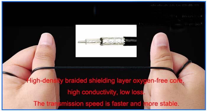
The Internal LTE Antenna PCB 4G Antenna comes with a 44x10mm printed circuit board compact size, 120mm length RG 1.13 cable, Ipex/MHF/u.FL connector, adhesive mount, and 2/4dBi gain internal LTE antenna for the 3G/4G LTE networks.
The Internal LTE Antenna PCB 4G Antennas are available at C&T RF Antennas Inc, the RF antennas LTE 4G antenna manufacturer in China.
C&T RF Antennas Inc provides the RF antennas with PCB & Flex PCB & Omni antenna types, covering the below frequencies:
5G NR PCB Antennas, LTE PCB Antennas, GSM PCB Antennas, Wifi PCB Antennas, NB-IoT PCB Antennas, LoRa PCB Antennas, GPS PCB Antennas;
5G NR FPC Antennas, 4G FPC Antennas, 3G FPC Antennas, NB-IoT FPC Antennas, Wifi FPC Antennas, GPS FPC Antennas, LoRa FPC Antennas;
5G Omni Antennas, 4G Omni Antennas, Wifi Omni Antennas, LoRa Omni Antennas; etc.
Contact us for more information on the Internal LTE Antenna PCB 4G Antenna such as Internal LTE Antenna PCB 4G Antenna datasheet, LTE Router Antenna 4G PCB Antenna pricing, Internal LTE Antenna PCB 4G Antenna inventory, or other 4G LTE antenna designs.
Internal LTE Antenna PCB 4G Antenna Specifications
Internal LTE Antenna PCB 4G Antenna Electrical Specifications |
|
| RF Antenna Type | PCB Antenna |
| Model | CTRF-ANTENNA-PCB-7027-4410-IPEX-120 |
| Frequency | 698-960MHz, 1710-2700MHz |
| Gain | 2dBi/4dBi |
| VSWR | ≤1.8 |
| Impedance | 50 Ω |
| Polarization | Vertical |
| Connector | U.FL |
| Lightning Protection | DC-Ground |
Internal LTE Antenna PCB 4G Antenna Mechanical Specifications |
|
| PCB Board Dimension | 40*15mm |
| Weight | Approx. 8g |
| Material | PCB Board |
| Operation Temperature | -40˚C ~ +85˚C |
| Storage Temperature | -40˚C ~ +80˚C |
| Color | Green |
| Antenna Design | Dipole Antenna |
| Mounting | Screw/Sticker |
| SafetyEmission and other | RoHS Compliant |
| Applications | ISM/SCADA/Utilities, IoT/NB-IoT/LoRa/M2M,
2G 3G 4G LTE/LTE-IoT, GSM GPRS |
We know that FDD and TDD are the abbreviations of frequency division duplex and time division duplex respectively.
FDD system means the system uses different frequencies for transmitting and receiving data, and there is a duplex interval between uplink and downlink frequencies, such as GSM, CDMA, and WCDMA systems are typical FDD systems;
A Time division duplex system is a system that uses the same frequency band for transmitting and receiving, and the uplink and downlink data are staggered in time, and the uplink and downlink data can be effectively avoided by sending in different time slots.
For example, TD-SCDMA is a TDD system.
When using TDD technology, it is relatively simple to estimate the channel characteristics based on each other’s signals as long as the upstream and downstream time interval between the base station and the mobile station is not large and smaller than the channel coherence time.
For the general FDD technology, the general upstream and downstream frequency interval is much larger than the channel coherence bandwidth, and it is almost impossible to estimate the downlink using the uplink signal and the uplink using the downlink signal; this feature makes the TDD way of mobile communication system has obvious advantages in power control and the use of smart antenna technology.
However, because of this, the coverage radius of the TDD system is smaller, and the base station coverage radius is significantly smaller than that of the FDD base station due to the upstream and downstream time intervals. Otherwise, the user signals at the edge of the cell will not be synchronized when they reach the base station.
Internal LTE Antenna PCB 4G Antenna Features

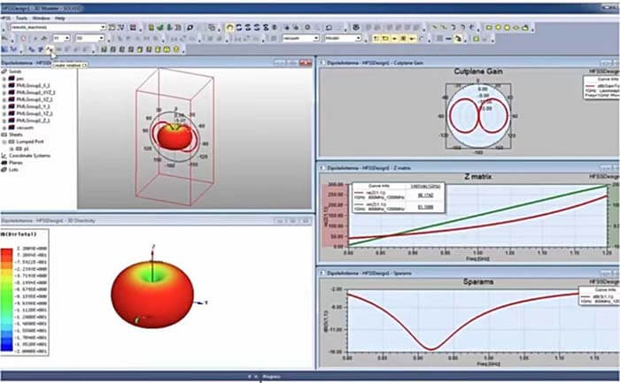
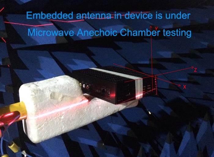
Customized Antenna Design
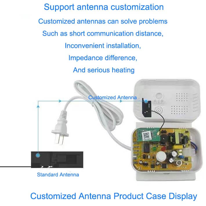
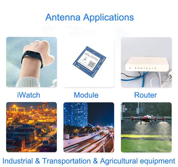

Reviews
There are no reviews yet.